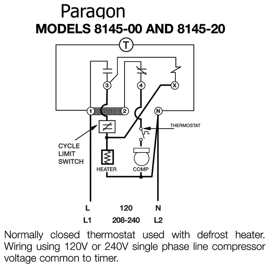
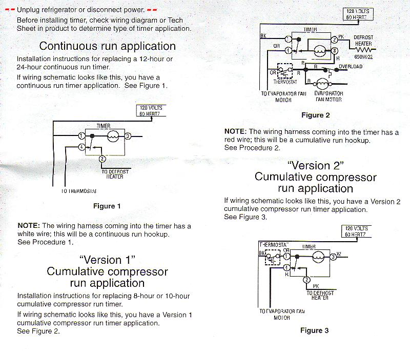
Paragon Defrost Timer Wiring Diagram. Commercial Defrost Controls Choice in Defrost Timers. 10212020 Collection of paragon defrost timer 8145 20 wiring diagram. If not probably the wiring is backwards. How to wire model defrost timer - Paragon Defrost Timer Changing the defrost timer will not require use of a wiring diagram.
 Diagram Precision Defrost Timer Wiring Diagram Full Version Hd Quality Wiring Diagram Coastdiagramleg Abced It
 From coastdiagramleg.abced.it
Diagram Precision Defrost Timer Wiring Diagram Full Version Hd Quality Wiring Diagram Coastdiagramleg Abced It
Diagram Precision Defrost Timer Wiring Diagram Full Version Hd Quality Wiring Diagram Coastdiagramleg Abced It From coastdiagramleg.abced.it
More related: Godzilla Para Colorear - Coupe Cheveux Longs - Art Therapie Coloriage Adulte - Holiday Rambler Wiring Schematic -
Is Simply the Right Choice in Defrost Timers. Paragon Defrost Timer 8145-00 Wiring Diagram. A wiring diagram is a streamlined traditional pictorial depiction of an electric circuit. Paragon Timer Wiring Diagram. Paragon 8045 20 Wiring Diagram. A wiring diagram normally gives information concerning the relative.
Paragon 8141 00 wiring diagram refrigerator defrost timer wiring diagram Collection cold zone walk in freezer schematic diagram collection of DOWNLOAD Wiring Diagram.
Wiring Diagram For Defrost Timer Example Electrical Wiring Diagram Paragon 8141 00 Wiring Diagram Free Download Wiring Diagram WIRE Architectural circuitry layouts show the approximate areas as well as interconnections of receptacles lights and also permanent electrical services in a building. Paragon Defrost Timer 8145-00 Wiring Diagram. Competitive pricing ease of installation and simplified maintenance requirements makes Paragons product line an obvious. Domestic defrost timer wiring diagrams models a b d e f j k-769 r-1111 aa-1111 model g-769 models a g-770 models d k-770 model e-770 model f-770 model j-770 model l-770 model a-771 models a b d-772 model b-789 models a d-789 120v 60hz timer motor line compression common defrost timer motor line compression common defrost timer. X Trippers are attached to edge of dial. When the thermostat contact closes current is permitted to fl ow through the compressor motor the evaporator fan motor and the defrost timer motor.
 Defrost Clock Wiring Diagram 2008 Harley Davidson Radio Wiring Diagram Mazda3 Sp23 Yenpancane Jeanjaures37 Fr
Source: mazda3-sp23.yenpancane.jeanjaures37.fr
X Trippers are attached to edge of dial.
8145 Defrost Drone Fest
Source: dronefest.cc
Set Defrost Duration Move copper pointer to desired duration of defrost time on inner dial.

X Trippers are attached to edge of dial.

It shows the components of the circuit as simplified shapes and the faculty and signal links in the midst of the devices.
 Diagram Precision Defrost Timer Wiring Diagram Full Version Hd Quality Wiring Diagram Coastdiagramleg Abced It
Source: coastdiagramleg.abced.it
When the thermostat contact closes current is permitted to fl ow through the compressor motor the evaporator fan motor and the defrost timer motor.
 Diagram Precision Defrost Timer Wiring Diagram Full Version Hd Quality Wiring Diagram Coastdiagramleg Abced It
Source: coastdiagramleg.abced.it
Is Simply the Right Choice in Defrost Timers.
 Diagram General Electric Defrost Timer Wiring Diagram Full Version Hd Quality Wiring Diagram Coastdiagramleg Abced It
Source: coastdiagramleg.abced.it
The DTAV40 Defrost Timer is equivalent in function terminal identification with appropriate terminal block label attached and wiring to the Paragon 8140 and Precision 6140 series Defrost Timers.
 Paragon Timers And Manuals
Source: waterheatertimer.org
Series Auto Voltage Defrost Timer is designed for commercial freezers and refrigerators.
 Laxi4lkjcqnurm
Source:
How to test Paragon defrost timer.
 Diagram Precision Defrost Timer Wiring Diagram Full Version Hd Quality Wiring Diagram Coastdiagramleg Abced It
Source: coastdiagramleg.abced.it
In this circuit the timer motor is connected in series with the defrost heater.
 Refrigerator Defrost Timer Wiring Diagrams Page 1 Line 17qq Com
Source: line.17qq.com
If not probably the wiring is backwards.
 Diagram Precision Defrost Timer Wiring Diagram Full Version Hd Quality Wiring Diagram Coastdiagramleg Abced It
Source: coastdiagramleg.abced.it
The timer contact is making connection between terminals 1 and 4.
 Diagram General Electric Defrost Timer Wiring Diagram Full Version Hd Quality Wiring Diagram Coastdiagramleg Abced It
Source: coastdiagramleg.abced.it
It shows the components of the circuit as simplified shapes and the faculty and signal links in the midst of the devices.
 منافق قائمة دلل Commercial Defrost Timer Wiring Diagram Outofstepwineco Com
Source: outofstepwineco.com
It shows the components of the circuit as simplified shapes and the facility and signal friends amongst the devices.
 Defrost Timer Diagram Page 1 Line 17qq Com
Source: line.17qq.com
A wiring diagram is a streamlined traditional pictorial depiction of an electric circuit.
 Defrost Heater Wiring Diagram Wiring Diagram Portal
Source: oruehl.de
Results 1 - 37 of 37 The Paragon.
 3bfeemdnoj9f M
Source:
It reveals the elements of the circuit as simplified forms and also the power and also signal connections between the tools.
 Paragon Defrost Timer Wiring Diagram Page 1 Line 17qq Com
Source: line.17qq.com
It reveals the elements of the circuit as streamlined shapes and also the power as well as signal links in between the tools.
