Nes Power Switch Wiring Diagram. Collection of poe switch wiring diagram. The rest of the external connectors are wired in. The wring information for the three position switch is here. 10212018 A wiring diagram typically provides information regarding the loved one placement and also setup of devices as well as terminals on the devices to assist in building or servicing the device.
More related: Immagini Pasquali Da Colorare - Ce Tech Cat5e Jack - Coiffure Pour Visage Rond - Dibujo Para Colorear De Frozen -
In diagram component T. 2272021 In the above diagram the power from the electricity source is coming through a two-wire cable to the first switch. I want to wire 1 way switch 1 dimmer switch with 2 individual lights from one powe source. Set the solder jumpers as required. Weve changed the diagram a bit now to show the start battery running through our new marine battery switch. I allows your house and start battery to remain isolated except for emergency conditions.
Switch wiring shows the Power Source Power In starts at the switch box.
How to Wire Two Light Switches With 2 lights with One Power Supply diagram. Describe and identify the diagram component U. In diagram component S. MAZDA WIRING DIAGRAMS WORKSHEET 1 1. Switch wiring shows the Power Source Power In starts at the switch box. Explanation of Wiring Diagram 1.
 Gameboy Style Reset Mechanism For The Nes 133mhz S Junk Box
Source: 133fsb.wordpress.com
In the diagram component Q.
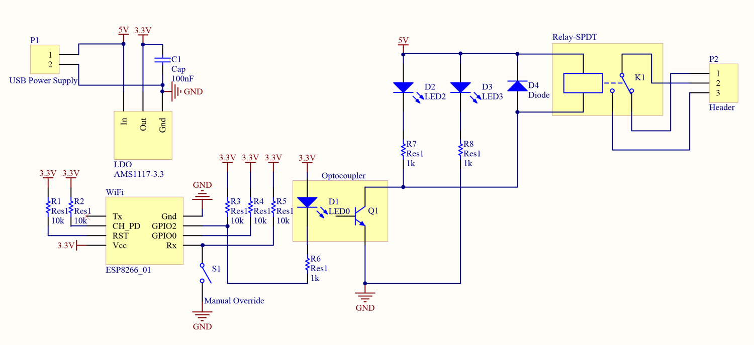 Wifi Power Switch
Source: christidis.info
Describe and identify the RB.
A Double Pole ONOFFCOMBINE battery switch like this one is a great choice for a single engine two battery boat wiring system.
 Ff 1609 Circuit Further Nes Top Loader Av Mod On Nes Power Switch Schematic Wiring Diagram
Source: dupl.benol.comin.gho.unho.phil.tool.iness.phae.plan.lious.bedr.targ.eumqu.embo.vish.ungo.sapebe.mohammedshrine.org
Switch wiring shows the Power Source Power In starts at the switch box.
 Zr 3244 Raspberry Pi Microusb On Off Power Switch Circuit By Mausberry Download Diagram
Source: teria.lite.lious.phae.mohammedshrine.org
How a 3-Way Switch Works.
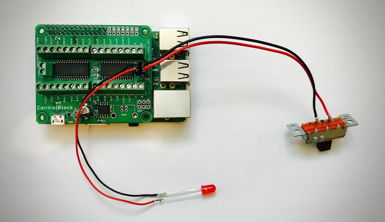 Tutorial Controlblock Retropie Snes And Nes Controllers
Source: petrockblock.com
UPS 230Vac Critical loads Non critical loads Emergency stop on ATyS Secured disconnection integrated for load isolation.
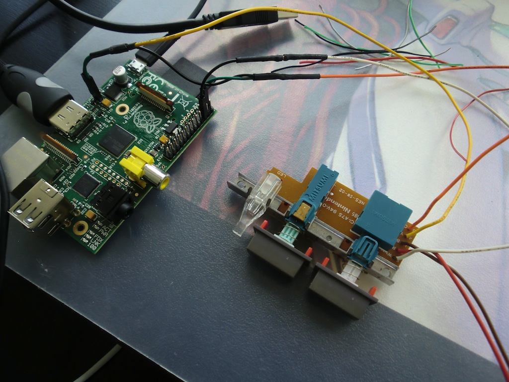
Describe and identify the diagram component U.
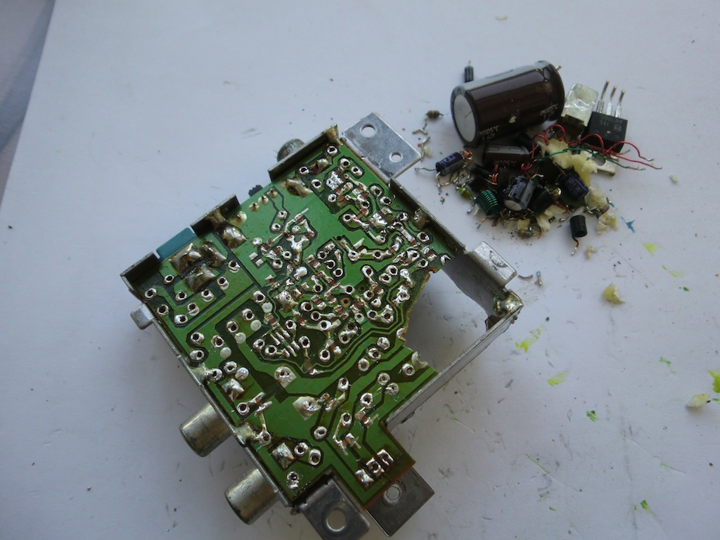
 Nintendo Nes Rf Module Removal Ampli Fi Blogampli Fi Blog
Source: blog.ampli.fi
In diagram component T.
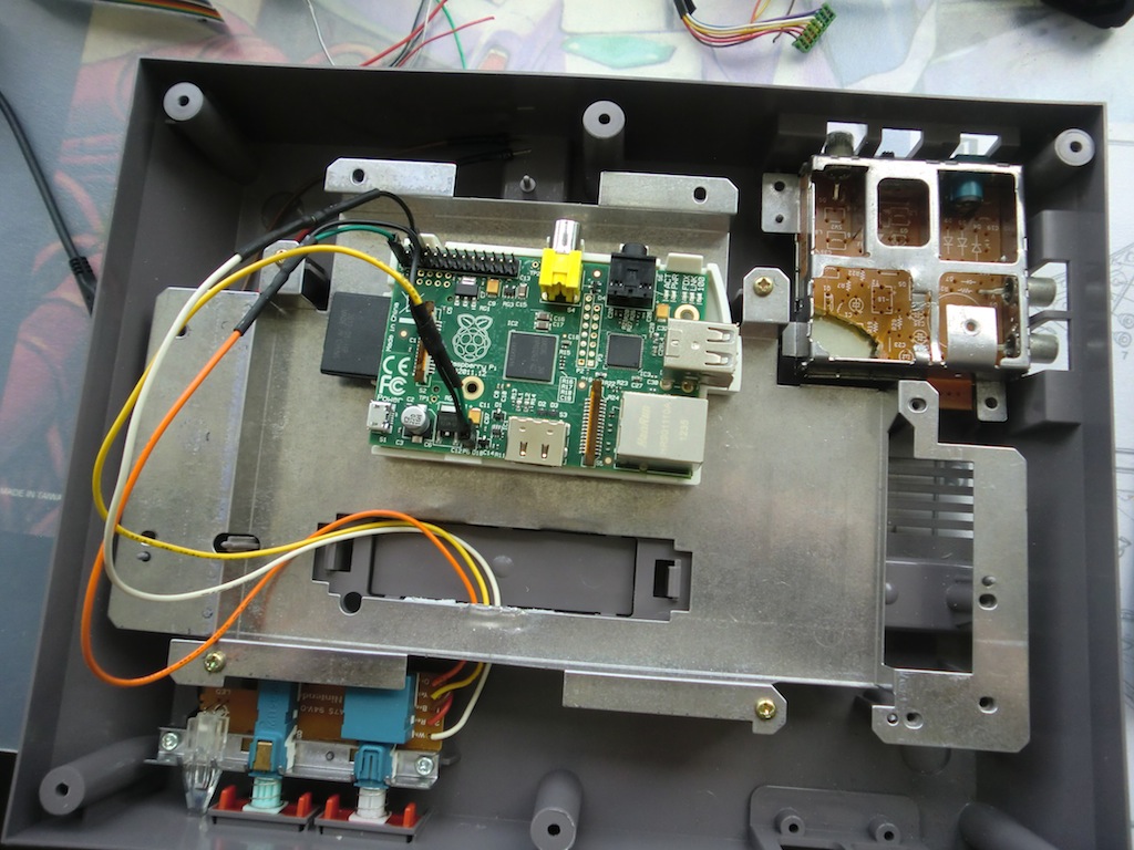
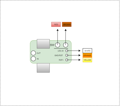 How To Wire Pi 3 To Nes Switch Retropie Forum
Source: retropie.org.uk
50- o Power Signal converter Coil signal to be I converted into on-off signal Fusible link Thermister Lamp Illuminated.
 Preparing The Parts Nintendopc
Source: mynintendopc.wordpress.com
2272021 In the above diagram the power from the electricity source is coming through a two-wire cable to the first switch.
 Nintendo Switch Controller Diagram Page 1 Line 17qq Com
Source: line.17qq.com
SYMBOLS IN THIS WIRING DIAGRAM SYMBOLS IN THIS WIRING DIAGRAM LOGICAL SYMBOLS Thc logical symbols are of four kinds.
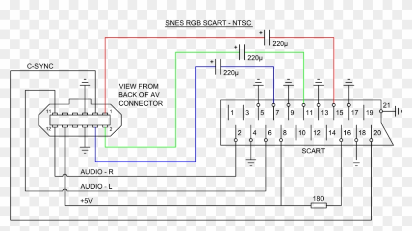 Nintendo 64 Av Cable Wiring Diagram Schematic Diagrams Snes Scart Hd Png Download 1300x700 1059106 Pngfind
Source: pngfind.com
The rest of the external connectors are wired in.
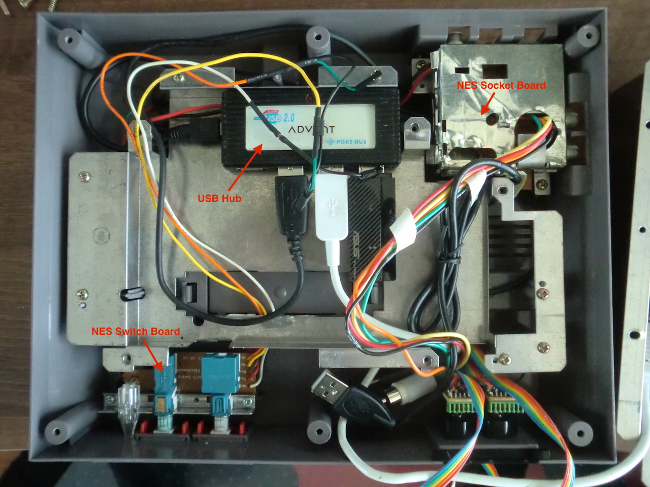
MAZDA WIRING DIAGRAMS WORKSHEET 1 1.
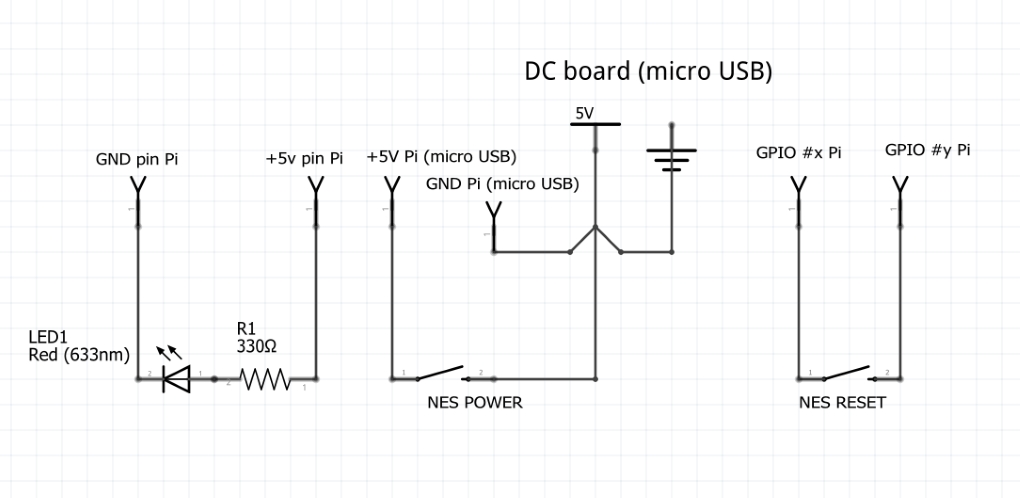 Nespi Project Part 5 Power And Reset Button Board Raspberryfield It Video Games And Comics
Source: raspberryfield.life
In diagram component T.
 Raspberry Pi In A Nes Case Wiring Revisited Igor Kromin
Source: igorkromin.net
Describe and identify the F.
 Preparing The Parts Nintendopc
Source: mynintendopc.wordpress.com
I want to wire 1 way switch 1 dimmer switch with 2 individual lights from one powe source.
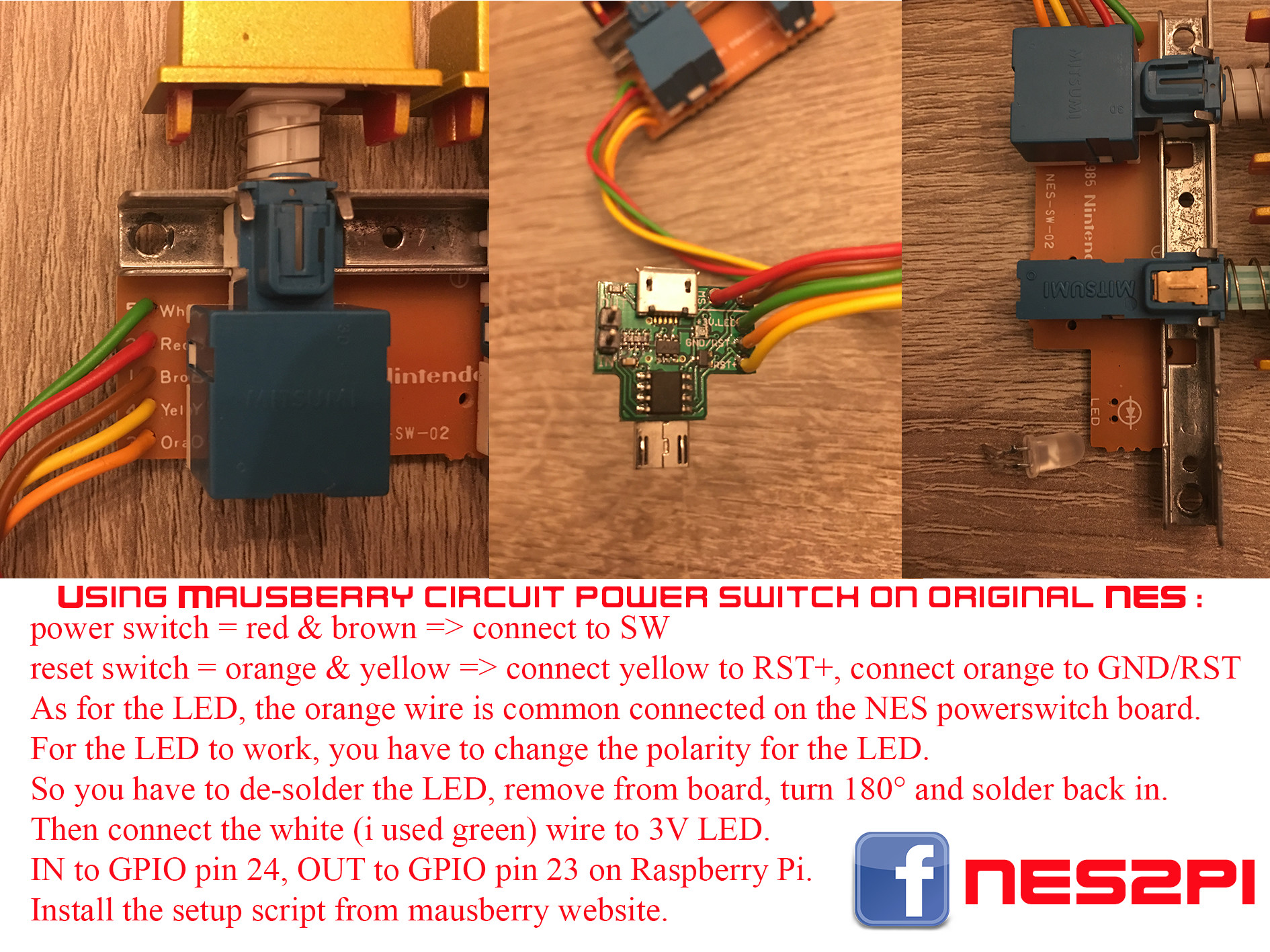 Mausberry Shutdown Circuit Nes Build Help Retropie Forum
Source: retropie.org.uk
As it goes through the red traveler it will stop at switch number one.
 Mausberry Shutdown Circuit Nes Build Help Retropie Forum
Source: retropie.org.uk
Wire up everything according to the wiring diagram.
