Murphy Switch Wiring Diagrams. Page 1 Typical Wiring Tech Sheet for Magnetic Switches and TATTLETALE. See if your engine is. Hourmeter _ B. Engine ground o o optional hourmeter op.
 Typical Wiring Tech Sheet For Magnetic Switches And Tattletale Annunciators Enovation Controls Help Center
 From support.enovationcontrols.com
Typical Wiring Tech Sheet For Magnetic Switches And Tattletale Annunciators Enovation Controls Help Center
Typical Wiring Tech Sheet For Magnetic Switches And Tattletale Annunciators Enovation Controls Help Center From support.enovationcontrols.com
More related: Coloriage Pokemon Carapuce - Cloture En Palette - 74hc14 Pinout - Coloriage A Imprimer La Belle Et La Bete -
Start Switch Alternator To Magnetic Sensor Alternator Tach Terminal or Signal Generator B Energized to Run PB128S Stop Switch Starter S B Exciter R Fuel Valve Typical Wiring Diagram with 760A and 761APH G NO R NC SW1 SW2 B 518PH Jumper B SIG GRD _ Distributor Ignition coil Fuel Valve Rack Pull Solenoid RP2300 Series shown Tachometer Hourmeter CLOSEDLOOP Wiring. 20t 518ph o optional voltmeter panel mount. CircleScout PumpProxy DC 2019 Control Unit for Engines with a 117 Murphy Switch Wiring Diagram. Fuse panel ground start button ammeter rear mew wire clip tag. Page 1 Typical Wiring Tech Sheet for Magnetic Switches and TATTLETALE. If optional tach andor hourmeter is used install flyback diodes as shown to reduce the potential of voltage spikes damaging soud state components.
It will keep power on from the NC.
This 12 volt model has a 30 second time delay and resets automatically when power is removed. Typical Wiring Diagram with 117117PH Magnetic Switch. Typical Wiring with 518E models. See if your engine is. But to get everything going you need a way to bypass it until it is operational. This 12 volt model has a 30 second time delay and resets automatically when power is removed.
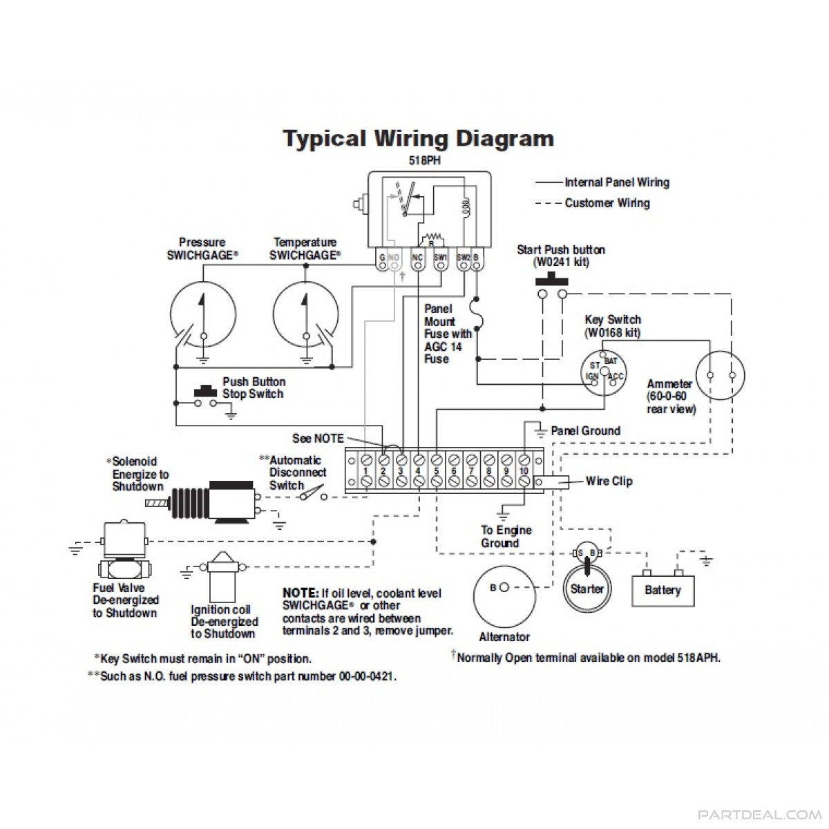 Diagram Normally Open Pressure Switch Wiring Diagram Full Version Hd Quality Wiring Diagram Coastdiagramleg Abced It
Source: coastdiagramleg.abced.it
This 12 volt model has a 30 second time delay and resets automatically when power is removed.
 Murphy Murphy Multi Purpose Tattletale Magnetic Switch With Dry Contacts Ms2100 Ms2100
Source: partdeal.com
The pre-calibrated package ensures your optimal performance and the integrated system simplifies installation.
Annunciator Panel Wiring Diagram
Source: wiringdiagramall.blogspot.com
892018 What is a Wiring Diagram.
Https Www Fwmurphy Com Uploaded Documents Pdfs 00 02 0191 Pdf
Source:
Start Switch Alternator To Magnetic Sensor Alternator Tach Terminal or Signal Generator B Energized to Run PB128S Stop Switch Starter S B Exciter R Fuel Valve Typical Wiring Diagram with 760A and 761APH G NO R NC SW1 SW2 B 518PH Jumper B SIG GRD _ Distributor Ignition coil Fuel Valve Rack Pull Solenoid RP2300 Series shown Tachometer Hourmeter CLOSEDLOOP Wiring.
 Murphy Switch Wiring Diagram 1998 Chevy Wiring Diagram Air Bag Carferra Genericocialis It
Source: air-bag.carferra.genericocialis.it
Pointer type contact rating.
 Murphy Murphy Tattletale Magnetic Switch 12 Volts 518ph 12 518ph 12
Source: partdeal.com
CircleScout PumpProxy DC 2019 Control Unit for Engines with a 117 Murphy Switch Wiring Diagram.
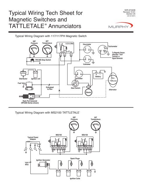 518ph Wiring Diagram
Source: yumpu.com
Murphy WD-03061B Wiring Diagram - WD300 Series Panels WD300.
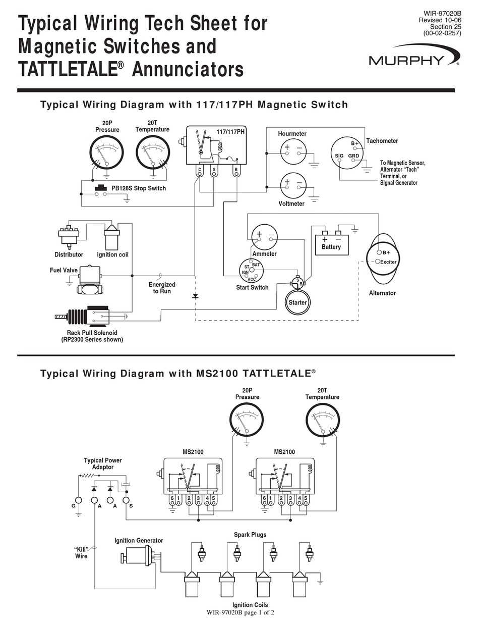 Murphy Tattletale Wir 97020b Wiring Instruction Pdf Download Manualslib
Source: manualslib.com
Youre going to wire it so the circuit going from engine 1 to the pivot now also has to go to engine 2.
 Typical Wiring Tech Sheet For Magnetic Switches And Tattletale Annunciators Enovation Controls Help Center
Source: support.enovationcontrols.com
Start Switch Alternator To Magnetic Sensor Alternator Tach Terminal or Signal Generator B Energized to Run PB128S Stop Switch Starter S B Exciter R Fuel Valve Typical Wiring Diagram with 760A and 761APH G NO R NC SW1 SW2 B 518PH Jumper B SIG GRD _ Distributor Ignition coil Fuel Valve Rack Pull Solenoid RP2300 Series shown Tachometer Hourmeter CLOSEDLOOP Wiring.
Https Www Fwmurphy Com Uploaded Documents Pdfs 00 02 0191 Pdf
Source:
A continued increase in temperature will complete the shutdown circuit.
 Typical Wiring Tech Sheet For Magnetic Switches And Tattletale Annunciators Enovation Controls Help Center
Source: support.enovationcontrols.com
When the high side preset high temperature point of the snap switch trips the NO.
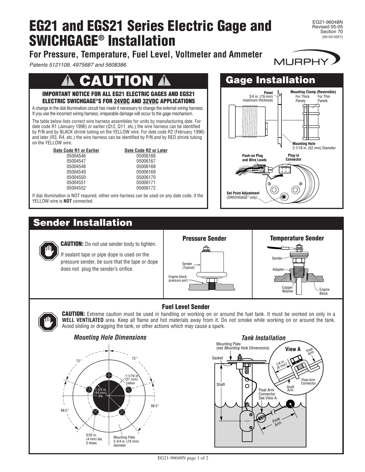 Murphy Switch Eg21 User Manual Manualzz
Source: manualzz.com
Start Switch Alternator To Magnetic Sensor Alternator Tach Terminal or Signal Generator B Energized to Run PB128S Stop Switch Starter S B Exciter R Fuel Valve Typical Wiring Diagram with 760A and 761APH G NO R NC SW1 SW2 B 518PH Jumper B SIG GRD _ Distributor Ignition coil Fuel Valve Rack Pull Solenoid RP2300 Series shown Tachometer Hourmeter CLOSEDLOOP Wiring.
 Typical Wiring Tech Sheet For Magnetic Switches And Tattletale Annunciators Enovation Controls Help Center
Source: support.enovationcontrols.com
It will keep power on from the NC.

Page 1 Typical Wiring Tech Sheet for Magnetic Switches and TATTLETALE.
 A20p A25p Series Fw Murphy Production Controls
Source: fwmurphy.com
Ad Search Murphy Switch Wiring.
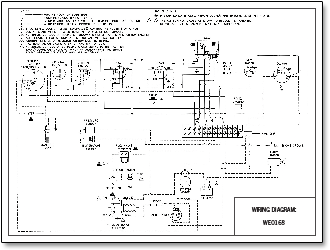 Install Wire Troubleshoot Fw Murphy W Series Engine Panels
Source: murcal.com
892018 What is a Wiring Diagram.
 Murphy Murphy Tattletale Magnetic Switch 12 Volts 518aph 12 518aph 12
Source: partdeal.com
Start Switch Alternator To Magnetic Sensor Alternator Tach Terminal or Signal Generator B Energized to Run PB128S Stop Switch Starter S B Exciter R Fuel Valve Typical Wiring Diagram with 760A and 761APH G NO R NC SW1 SW2 B 518PH Jumper B SIG GRD _ Distributor Ignition coil Fuel Valve Rack Pull Solenoid RP2300 Series shown Tachometer Hourmeter CLOSEDLOOP Wiring.
 20p 25p Series Fw Murphy Production Controls
Source: fwmurphy.com
Fuse panel ground start button ammeter rear mew wire clip tag.
