Gamecube Controller Diagram. Cable shielding ground. You will need the GC controller and plug in the next step. They are denoted as T1 T2 and T3 which mainly represents the different stick mechanisms or stickboxes as its the most important component of the controller. The oscilloscope trace below shows a typical probe sequence with the scope triggered on the negative edge.
 Powera Wireless Controller For Nintendo Switch Gamecube Style Purple Walmart Com Gamecube Controller Wireless Controller Gamecube
 From pinterest.com
Powera Wireless Controller For Nintendo Switch Gamecube Style Purple Walmart Com Gamecube Controller Wireless Controller Gamecube
Powera Wireless Controller For Nintendo Switch Gamecube Style Purple Walmart Com Gamecube Controller Wireless Controller Gamecube From pinterest.com
More related: Barbie Da Colorare - Ninja Zum Ausmalen - Coloriage Peppa Pig Halloween - Tom Und Jerry Ausmalbild -
Usually the same ground of pin 3. If you are using a Gamecube controller run the calibration fixer tool. This membrane has a path leading to the terminal for each function. 2202020 The diagram shows a button-like thing on the lower part of the breadboard connecting pin 8 to GND but its never mentioned in the guide. With no controller attached the gamecube probes for a controller by sending the sequence 000000001 about every 12ms. Safety Precautions - Web page.
Perform calibration using the control panel tool See calibration below.
Also available for Switch Pro controller PS4 Xbox Series XS Xbox One Stadia and Joycon grip. Authored by Francisco Martin and Andrew Smith. Live worry free knowing your buttons and joysticks are protected. Usually the same ground of pin 3. If you are using a Gamecube controller run the calibration fixer tool. Cable shielding ground.
 Gamecube Controller Hycarus White Game Cube Controller Amazon In Electronics
Source: amazon.in
For that reason Gamecube architects came up with a new memory system strictly based on providing dedicated memory space and using low-latency chips.
 Powera Wireless Controller For Nintendo Switch Gamecube Style Purple Walmart Com Gamecube Controller Wireless Controller Gamecube
Source: pinterest.com
The GameCube controller saw two major redesigns of its internals.
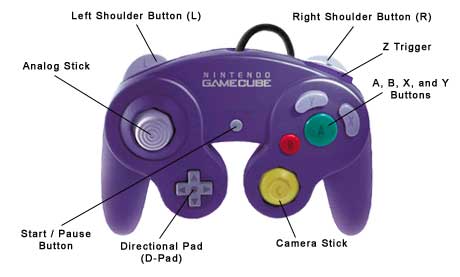 Where Is The Z Button For Gamecube Games
Source: forums.dolphin-emu.org
This membrane has a path leading to the terminal for each function.
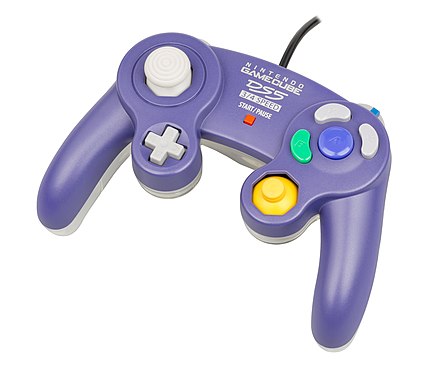 Gamecube Controller Wikiwand
Source: wikiwand.com
The controller connects to the Gamecube through a proprietary 6-pin connector with screened cable.
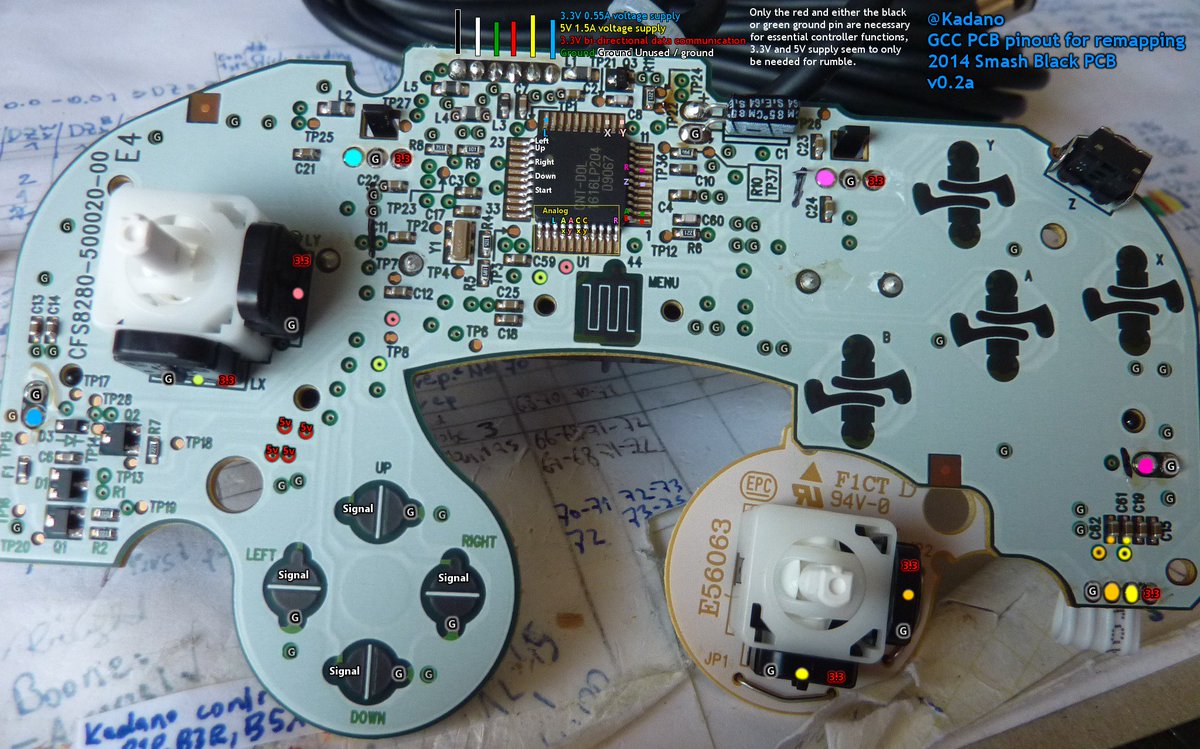 Kadano On Twitter Gamecube Controller Pcb Pinout Documentation Https T Co Z8jaely4kh
Source: twitter.com
When you connect a controller it will respond to this sequence so you know that it is attached.
 Wired Controller For Nintendo Switch Gamecube Style Black Powera
Source: powera.com
The GameCube controller saw two major redesigns of its internals.
File Gccontroller Layout Svg Wikipedia
Source: en.wikipedia.org
Ground Extrme Skillz GC to USB interface has pins 34 wired as common ground.
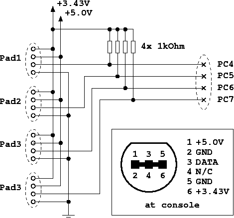 Ezhid Gamecube Controller Firmware
Source: ezhid.sourceforge.net
Leave at least 2 inches from plug.
 Reiso For Wireless Gamecube Controller 2 4g Gc Controller With Receiver Adapter Compatible Nintendo Gamecube Wii Black And Blueviolet Amazon Ca Electronics
Source: amazon.ca
The Nunchuck can be trashed.
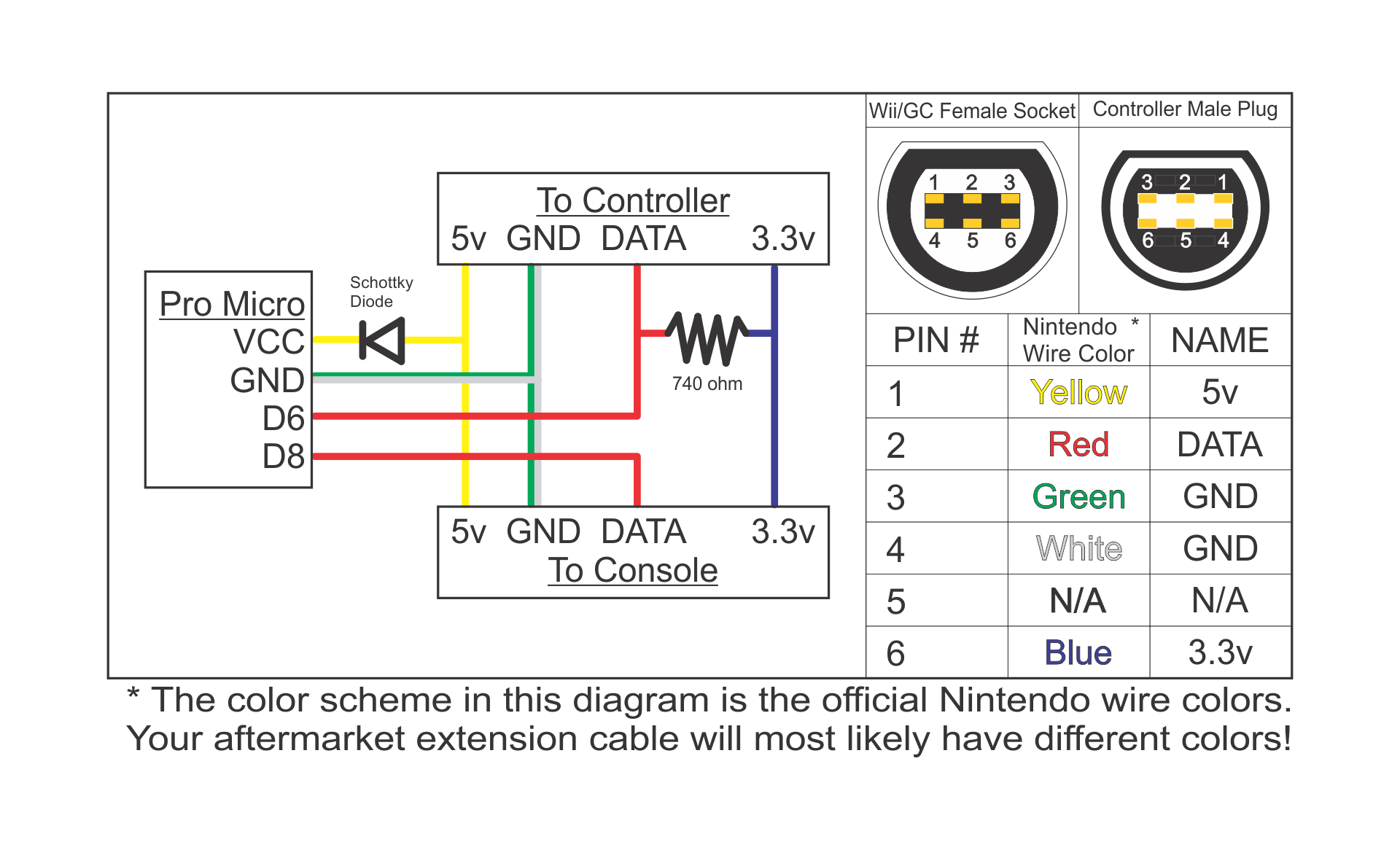 Github Skuzee Ess Adapter An Adapter To Make Gamecube Controllers Feel More Like N64 Controllers For Use With Gamecube Wii Virtual Console Etc
Source: github.com
Ground Extrme Skillz GC to USB interface has pins 34 wired as common ground.
 Powera Wired Controller For Nintendo Switch Gamecube Style Purple Nintendo Switch Amazon Ca Computer And Video Games
Source: amazon.ca
To send a 0 I configure it as output-low.
 Nintendo Super Smash Bros Edition Gamecube Controller For Wii U Black Wupackb1 Best Buy Gamecube Controller Nintendo Super Smash Bros Gamecube
Source: pinterest.com
The Gamecube controller uses 33V logic bidirectional 33V to power the controller and 5V for the rumble motor.
Diagram Gamecube Controller Wiring Diagram Right Stick Full Version Hd Quality Right Stick Codetodiagram Cappadociaweb It
Source: codetodiagram.cappadociaweb.it
They are denoted as T1 T2 and T3 which mainly represents the different stick mechanisms or stickboxes as its the most important component of the controller.
 Drawn Controller Gamecube Nintendo Gamecube Controller Png Transparent Png Vhv
Source: vhv.rs
Introduction h2.
 Wireless Gamecube Controller For Nintendo Switch Overview Setup Powera
Source: support.powera.com
Seven 7 pin Nintendo GameCube controller connector.
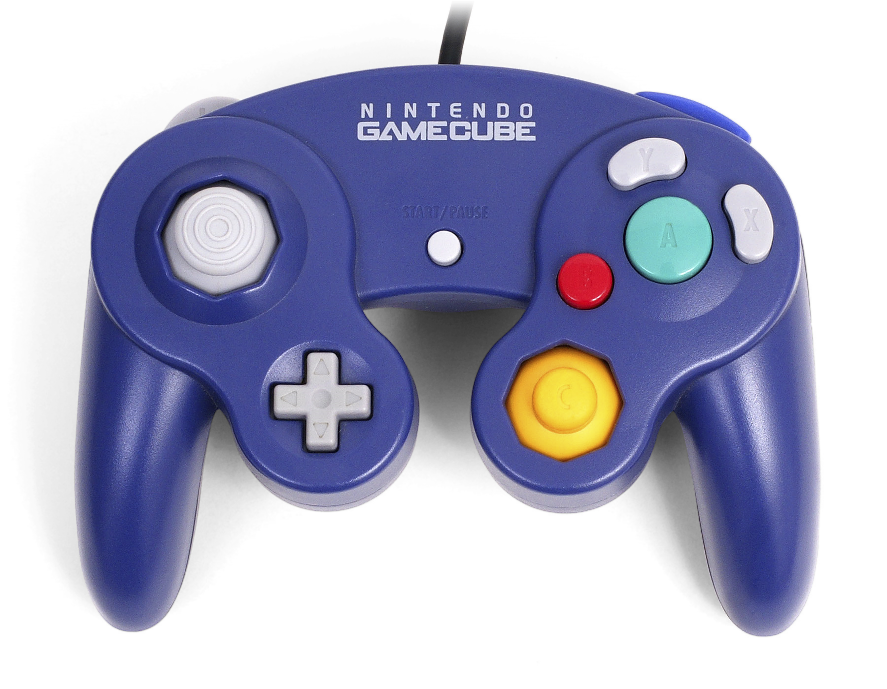 Gamecube Controller Ultimate Pop Culture Wiki Fandom
Source: ultimatepopculture.fandom.com
Safety Precautions - PDF.
 Gamecube Controller Hycarus White Game Cube Controller With Turbo And Slow Buttons Gamecube Controller Switch Edition For Nintendo Gamecube Controller Games Gamecube Adapter Required Amazon Sg Electronics
Source: amazon.sg
Leave at least 2 inches from plug.
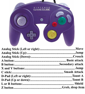 One Duck S Opinion Super Smash Bros Brawl Review Part 1 The Controls
Source: one-ducks-opinion.blogspot.com
Check out the worlds first clip-on Gamecube controller carrying case.
