Frc Pneumatics Diagram. Pneumatics uses pressurised gas to move things. For most cases a Compressor object does not need to be instantiated or used in a robot program. The compressor doesnt necessarily have to be on the robot but must be powered by the robots PCMs. FIRST Robotics Competition.
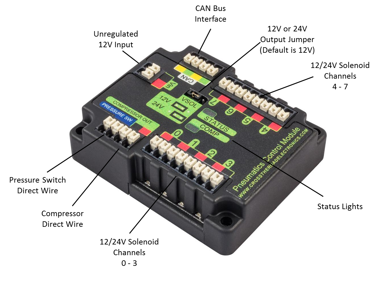 Pneumatic Control Module Pcm Faq Frc 2168 Roborio Beta Test This Is The Main Website For Team 2168 2015 Frc Control System Documentation This Website Will Contain Information Team
 From khengineering.github.io
Pneumatic Control Module Pcm Faq Frc 2168 Roborio Beta Test This Is The Main Website For Team 2168 2015 Frc Control System Documentation This Website Will Contain Information Team
Pneumatic Control Module Pcm Faq Frc 2168 Roborio Beta Test This Is The Main Website For Team 2168 2015 Frc Control System Documentation This Website Will Contain Information Team From khengineering.github.io
More related: Decorer Boite Conserve - Joker Para Colorear - Lol Da Stampare - Cristaux De Neige Dessin -
FRC Pneumatic System Layoutpdf 10020 KB. 1092019 FRC Pneumatic System Diagram. FIRST Robotics Competition. In FRC pressure is created using a pneumatic compressor and stored in pneumatic tanks. The Physical Layer ii. Pneumatics uses pressurised gas to move things.
The module is connected to the roboRIO over the CAN bus and powered via 12V from the PDP.
Learn with flashcards games and more for free. It is being provided as a courtesy and therefore does not supersede any information or rules provided in the FIRST Robotics Competition Manual. In FRC pressure is created using a pneumatic compressor and stored in pneumatic tanks. Know the Block Diagram 1. Basic introduction to the components of the FIRST Robotics Competition electrical system. For most cases a Compressor object does not need to be instantiated or used in a robot program.
A Bunch Of Hot Air Or How To Kind Of Know What You Re Talking About In Frc Pneumatics Pneumatics Chief Delphi
Source: chiefdelphi.com
FRC Pneumatic System Layoutpdf 10020 KB.
Http Team358 Org Files Pneumatic Pneumatics Stepbystep Roborio Pdf
Source:
This guide was made with the power of.
Source: docs.wpilib.org
The Closed Loop mode on the Compressor is enabled by default and it is not recommended that teams change this setting.
 Frc Pneumatics Diagram Quizlet
Source: quizlet.com
FRC Pneumatic System Layout-2png 20001391 603 KB.
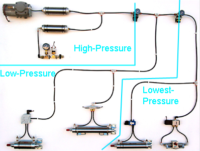 Team358 Org Robotic Eagles First Robotics Competition
Source: team358.org
Note that in many FRC games robot-to-robot contact may be substantial and Dual Lock.
 Layout Of Off Board Compressor Featuring Sweet Pics Pneumatics Chief Delphi
Source: chiefdelphi.com
It will also apply to all first or second year FIRST robotics teams who have never used pneumatics or to anyone who wants to add pneumatics to.
 Pneumatics Performance Kit Andymark Inc
Source: andymark.com
General Wiring Diagram 14.
 Pneumatic Control Module Pcm Faq Frc 2168 Roborio Beta Test This Is The Main Website For Team 2168 2015 Frc Control System Documentation This Website Will Contain Information Team
Source: khengineering.github.io
Frc Pneumatic Wiring Diagram Wiring Diagram Frc Wiring Diagram.
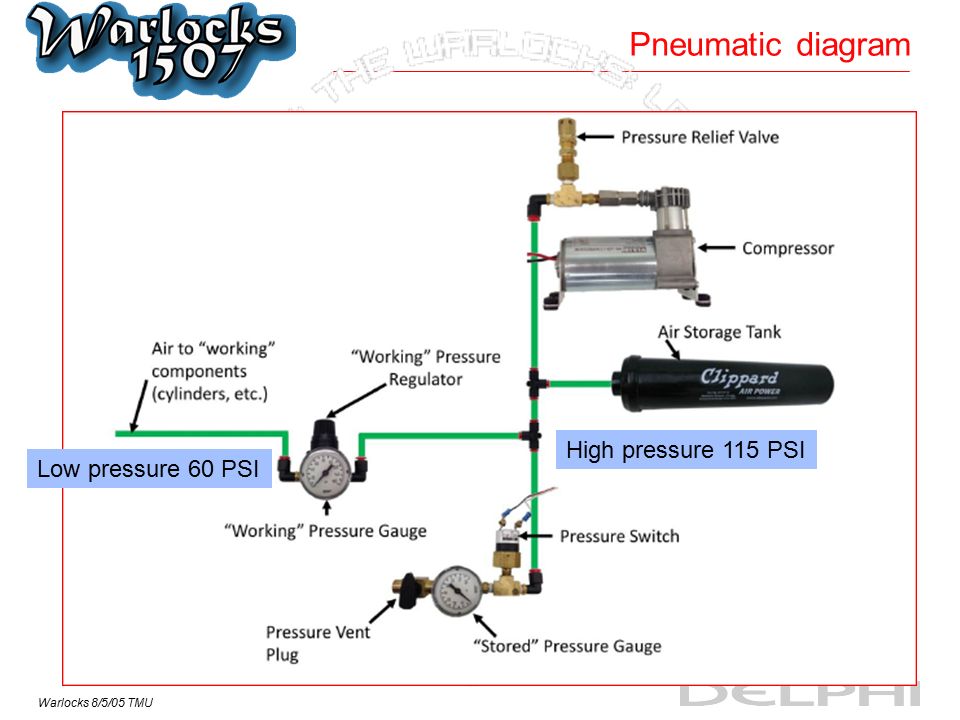 Warlocks 8 5 05 Tmu Pneumatics On Robots U Simplified Model Compressed Air Tank Geek Safety Glasses 60 Lbs Pneumatic Cylinder Whoa That S A Lot Of Force Ppt Download
Source: slideplayer.com
A single PCM will support most pneumatics applications providing an output for the compressor input for the pressure switch and outputs for up to 8 solenoid channels 12V or 24V selectable.
 Pneumatic Control Loop Vi Labview Pneumatic Control Loop Documentation
Source: documentation.help
Let me know if something is missing or if you have any other suggestions.
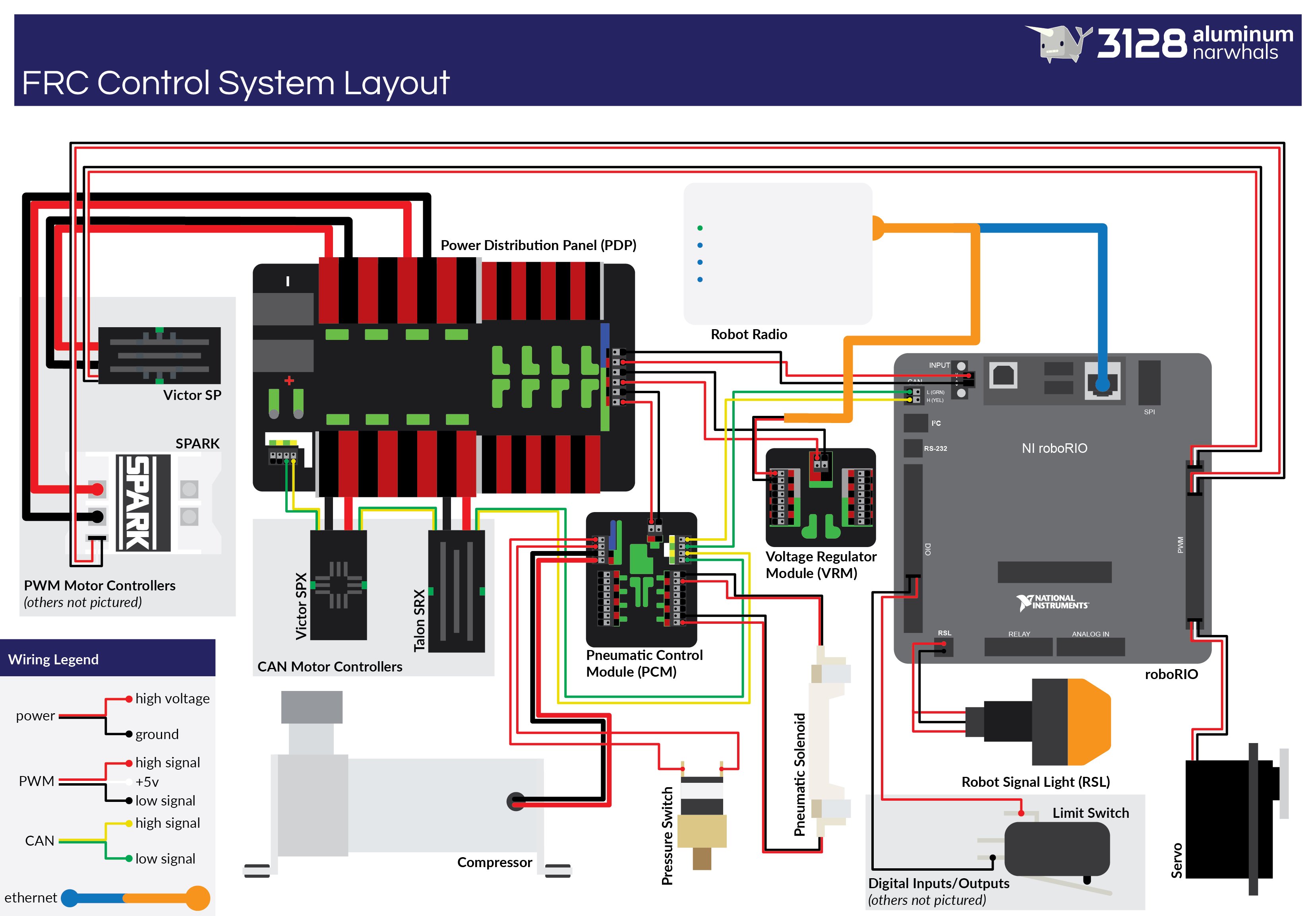 Diagram Crio Frc Wire Diagram Full Version Hd Quality Wire Diagram Outletdiagram Calatafimipartecipa It
Source: outletdiagram.calatafimipartecipa.it
Basic introduction to the components of the FIRST Robotics Competition electrical system.
 How To Create A Pneumatic System For F I R S T Robots 7 Steps Instructables
Source: instructables.com
The Closed Loop mode on the Compressor is enabled by default and it is not recommended that teams change this setting.
Http Www Team358 Org Files Pneumatic 2014frcpneumaticsmanual Pdf
Source:
Youll be capable to learn exactly when the assignments should be finished that makes it easier for you personally to correctly manage your time.
 N Yw2r6gkqafjm
Source:
A single PCM will support most pneumatics applications providing an output for the compressor input for the pressure switch and outputs for up to 8 solenoid channels 12V or 24V selectable.
 Pneumatic Power Principles Of Engineering 2012 Project Lead
Source: slidetodoc.com
This is an instructable primarily for next years members of the Scarlett Robotics team 4733 however.
Frc Pneumatic System Diagram Control System Chief Delphi
Source: chiefdelphi.com
We created this guide in hopes of combining a basic understanding of all the electronic.
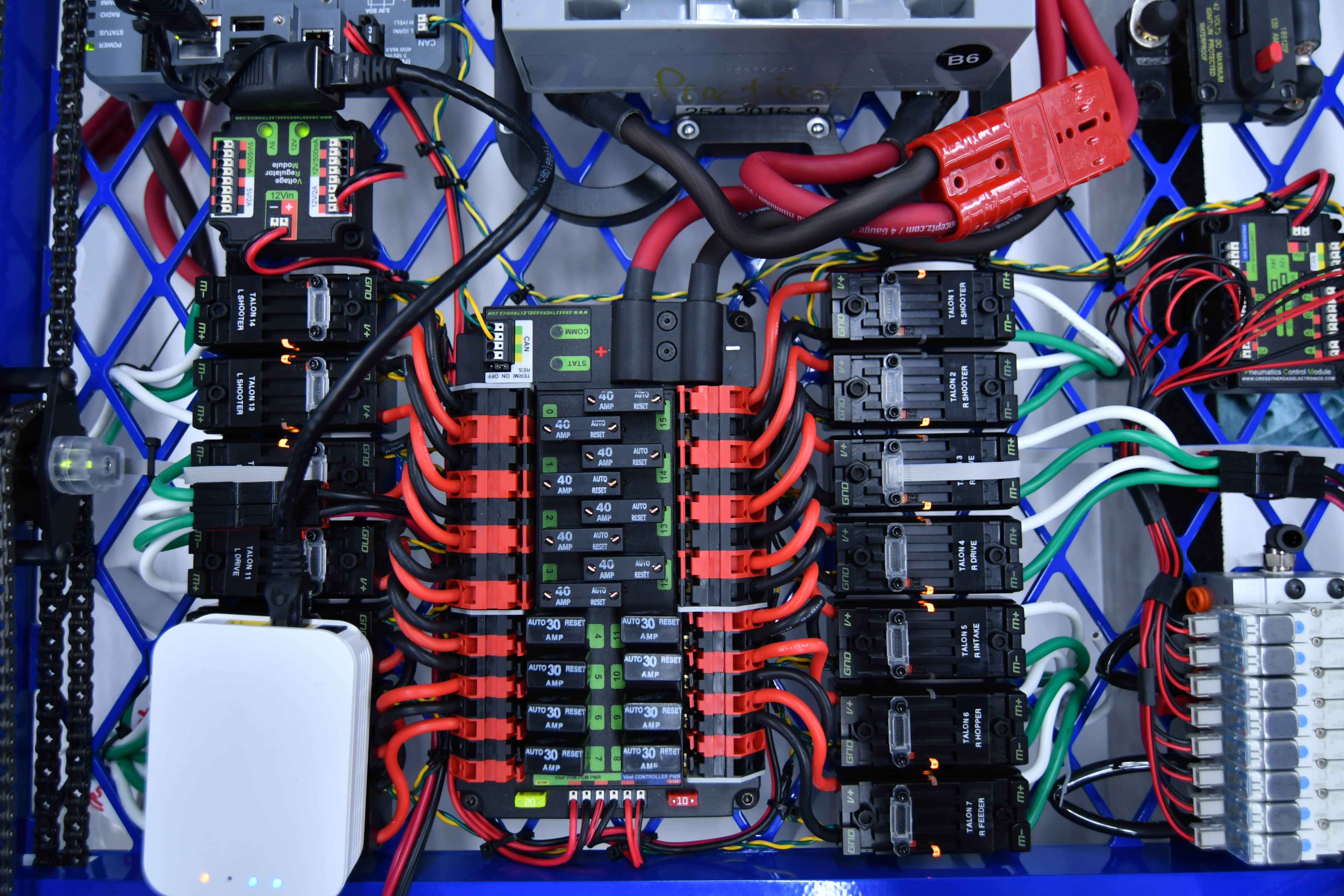 Diagram Crio Frc Wire Diagram Full Version Hd Quality Wire Diagram Outletdiagram Calatafimipartecipa It
Source: outletdiagram.calatafimipartecipa.it
The PCM will automatically run in closed loop mode by default whenever a Solenoid object is created.
Http Team358 Org Files Pneumatic Pneumatics Stepbystep Roborio Pdf
Source:
Learn with flashcards games and more for free.
